|
ZC1 M2 Wireless Set
WS ZC1 MkII Mk11 MK II Mk 11 Mark 2
Transmitter Receiver
|
|
Circuit Diagram, Service
Manual, Service
Information, Schematic Diagrams and Manuals |
|
For Repairing, Restoration and
Servicing of Vintage and Modern Electronic Equipment |
|
Manual and
Circuit
available
Details Below
As a Download
Click Here
|
|
Circuits
& Manuals
Military,
Radio, TV,
Amateur & Marine
World Wide Service
For
Lists Click Here
|
|
Use R/H scroll Bar
More information
below
Radio's For Sale
Click Here
Military and
Broadcast
Radio Ads Click
Here |
|
Military Radio Home
Click
Here If no Index to the left
|
ZC1 M2Wireless Set
Transmitter Receiver
WS ZC1 MkII Mk11 MK II Mk 11 Mark 2
The ZC1 M2 Wireless Set was designed
to replace the ZC1 M1 providing additional facilities particularly in
connection with WT.The set was partly tropicalised and was for use on the
ground or in a vehicle.
With Amplifier RF No ZA1 MK 2 it provided longer
range and air support communications." |
|
The Range of working will vary
with frequency and the type of aerial used.
Typical ground wave ranges in
miles which may be expected between moving vehicles are as follows.
- RT 15 to 20 miles
- CW 20 to 25 miles
|
|
The sender and receiver are both
designed to operate on any frequency between 8 mc/s and 2 mc/s in two
bands.
- HF Band 8.0 to 4.0 mc/s
- LF Band 4.0 to 2.0 mc/s
|
|
|
The sender output power varies
between 1.6 and 2.0 watts depending on frequency and the type of aerial
used.
The set is fitted for break in operation on MCW or CW. A BFO
provides resolution of CW signals.
On CW and MCW the volume control
becomes an RF gain control.
Power Supply for the set is from two 6 volt 85
Ah batteries in series providing 12 volts.
Current taken as follows.
|
Manual and
Circuit
available
Details Below
As a Download
Click Here |
ZC1
Mk 2 maintenance manual of 64 A4 pages.
Containing the following :-
General Description
Purpose
Range
Description
Power Supply
Aerials
Operation of set
Introduction
Station in Truck
Ground Station
Description of Tuning Dials
Receiver operation
Receiver Flick adjustment
Crash Limiter
Sender operation (Control Station)
Sender operation (Out Station)
Netting
Netting to a Wavemeter
Break in Operation
Flick Working changing system of Transmission & Wireless Silence
Remote Control Unit
General
Description
Weight
Working instructions Remote Control
Connecting Up
Operation with Two Control units
Operation one Control Unit and Exchange
Operation two Control Units and Exchange
Adjustment of Buzzer
Looking after the Set
Your Job
Connecting up the set and changing parts
Maintenance
Tables
Tests
Running Repairs
Tables of Switching
Appendices
Selection and Use of Aerials
Table of Component Values
Station List
Weight and Dimensions
Plates (images)
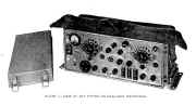
General View of Set on Resilient Mountings
Mobil Station
Ground Station
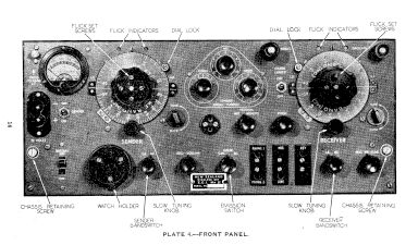
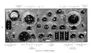
Front Page
Remote Control Unit
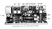
Top View out of case
Diagrams
Fitting Aerial Base No 8
Erection of 32 ft Aerial
Carrying Aerial
Receiver Controls
Tuning to Zero Beat
Sender Controls
Connecting Remote Control Unit to Set
Valve Container
Complete Station in Truck
Complete Station on Ground
Schematic Remote Control Unit
Schematic Wireless Set No ZC1 Mk 2
It is comprehensive and gives all the relevant information to renovate operate and maintain the ZC1
Mk 2 Wireless Set. |
ZC1 M2Wireless Set
Transmitter Receiver
WS ZC1 MkII Mk11 MK II Mk 11 Mark 2
Manuals are Available Worldwide as a
Download.
Working
Instructions containing 64 pages including the Circuit with Component values
and a top chassis view.
Manual
64 A4 pages worldwide
( For all Payment Options )
( Please Click the Payment Links Below |
|
We do all we can to provide
the very best that is available for you.
But in the unlikely event that any data should not be as you expected.
A refund is always available. Kind Regards Allen and Alanna. |
|