|
Telequipment Oscilloscope D1015
D1016
|
|
Circuit Diagram, Service
Manual, Service
Information, Schematic Diagrams and Manuals |
|
For Repairing, Restoration and
Servicing of Vintage and Modern Electronic Equipment |
|
Maintenance
Manual with
Circuits and
Operation Instructions
Details Below
As a Download
Click Here
|
|
Circuits
& Manuals
Military,
Radio, TV,
Amateur & Marine
World Wide Service
For
Lists Click Here
|
|
Use R/H scroll Bar
More information
below
Radio's For Sale
Click Here
Military and
Broadcast
Radio Ads Click
Here |
|
Military Radio Home
Click
Here If no Index to the left
|
Telequipment D1015 D1016 Oscilloscope
Manuals
also available for the following models :-
S22, D31, D31R, S31, S31R, D32,
S32A, S32AR, D43,
D43R, S43, D51, S51,
D52, S52, D54, D54R,
D56, D61,
D61A, DM63, DM64, D65, D66,
D67, D67A, D80, D83,
D1010, D1011, D1015, D1016 & Serviscope Minor.
Click
Here
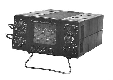
This Instruction Manual describes the Performance, Operation and Servicing of Oscilloscope Types D1015 and D1016. These are lightweight 15MHz
a.c. mains powered, dual trace instruments, with a single time base and two identical vertical amplifiers. The scanning area is 8x 10cm and has a time and voltage measurement accuracy of 5%.
The use of solid state circuitry incorporating integrated circuits and field-effect transistors minimises drift and provides fast stabilization time.
The facilities include a single trace display, or dual trace display with the two channels either chopped or alternated, and an external X mode.
Type D1016 has the additional facilities of (a) switching one channel for true X—Y display, (b) algebraic addition of two input signals, (c) variable control of sweep speeds between the marked positions of the SECS/DIV switch.
|
|
|
The Manual Contains the
Following :-
SPECIFICATION
Cathode Ray Tube
Vertical Amplifiers
Horizontal Deflection
Cal Output Socket
General
OPERATION
General
Mechanical Features
Controls and Connection Sockets
CRT Graticule
Operating Voltage
Power Cord
First Time Operation
Setting the Controls
Switch On
Input Signal Coupling DC-GND-AC
Triggering
Trigger Level
Trigger Source
X—Y Display (DlOl6Only)
Chop and Alternate Modes
EXT X
APPLICATIONS
General
Probe Adjustment
Peak to Peak Voltage Measurement
Voltage Measurement between Two Points
Instantaneous Voltage Measurement with Reference to Ground
Instantaneous Voltage Measurement with Reference to a DC Voltage
Time Duration Measurement
Frequency Measurement
Rise Time
Correction Formula for Fast Rise Time Waveforms
Phase Difference Measurement
CIRCUIT DATA
Introduction
Block Diagram-Circuit 1
CH1 and CH2 Vertical
Attenuators — Circuits 2-1, 2-2
Vertical Pre-Amplifier and
Channel Switching — Circuit 3
Vertical Output Amplifier — Circuit 4
Trigger Amplifier — Circuit 5
Sweep Generator — Horizontal Amplifier — Calibrator — Circuit 6
Power Supply — CAT — Blanking — Circuit 7
Interconnection Diagram — Circuit 10
WIRED ASSEMBLIES
Introduction
Circuit Boards
Part Numbers
PC242 - PC247 - PC253
PC244
PC245
PC246
MECHANICAL PARTS
Parts List
Mechanical Assembly View 1
Mechanical Assembly View 2
MAINTENANCE AND FAULT FINDING
Introduction
Preventive Maintenance
General
Corrective Maintenance
General
Component Replacement
Dismantling Procedures
Top Cover Removal
Bottom Cover Removal
Vertical Amplifier Unit Removal
Electrical Shield (Vertical Unit) Removal
Horizontal Amplifier Unit Removal
Electrical Shield (Horizontal Unit) Removal
Heatsink Rear Panel Removal
Power Supply Board PC246 Removal
CRT Removal
Mains Board PC247 Removal
Front Bezel Removal
Handle Removal
Power Supply Fault-Finding and Repair
Equipment
Supply Malfunctioning
Fault-Finding Procedure
CR1 Blanking Procedure
RE-CALIBRATION
Introduction
General
Calibrator
Tools and Equipment
RE-CALIBRATION PROCEDURE
Initial settings
DC Supply Line Voltages
CRT Controls
Vertical Amplifier
CH1 and CH2 Gain and
Volts /Div Balance
x5 Gain Balance (D1016 only)
Vertical Amplifier Input Compensation
X—Y Gain and Balance (D1016) only
Vertical Amplifier High Frequency Compensation
Internal Calibrator
Sweep Accuracy
Trigger Sensitivity
STANDARD OPTIONS AND ACCESSORIES
Introduction
Standard Options
Accessories
|
Maintenance
Manual with
Circuits and
Operation Instructions
Details Below
As a Download
Click Here
|
|
Maintenance
Manual with
Circuits and
Operation Instructions
Details Below
As a Download
Click Here
|
Telequipment D1015
D1016 Oscilloscope
Manuals are Available Worldwide as a
Download.
The
Manual contain 79 pages including Circuits
Component lists and Layouts
Manual
79 A4 pages worldwide
( For all Payment Options )
( Please Click the Payment Links Below )
|
|
We do all we can to provide
the very best that is available for you.
But in the unlikely event that any data should not be as you expected.
A refund is always available. Kind Regards Allen and Alanna. |
|