|
TF2330 Marconi Wave
Analyser
|
|
Circuit Diagram, Service
Manual, Service
Information, Schematic Diagrams and Manuals |
|
For Repairing, Restoration and
Servicing of Vintage and Modern Electronic Equipment |
|
Manual
Circuit and
Operation Instructions
available
Details Below
As a Download
Click Here
|
|
Circuits
& Manuals
Military,
Radio, TV,
Amateur & Marine
World Wide Service
For
Lists Click Here
|
|
Use R/H scroll Bar
More information
below
Radio's For Sale
Click Here
Military and
Broadcast
Radio Ads Click
Here |
|
Military Radio Home
Click
Here If no Index to the left
|
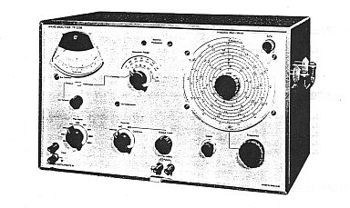
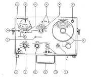
TF2330 Marconi Wave Analyser
The TF 2330 Wave Analyser provides comprehensive measurement facilities for the analysis of the performance of devices operating within the audio and ultrasonic frequency spectrum. The amplitude of each individual frequency component of a complex signal may be determined in terms of absolute voltage or relative to a fundamental datum level in decibels or in percent.
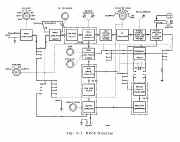
Basically the instrument comprises a sensitive narrow band tuned voltmeter covering the range 3 p.V to 300 V. With a bandwidth of 7 c/ s it may be tuned to any frequency from 20 c/s to 50
kc/s; after initial tuning internal automatic frequency control may then be employed to lock it to the signal component to obviate continual retuning, thus ensuring accurate meter readings.
While a signal is being investigated a variable output voltage is available, having the same frequency as the signal component to which the Analyser is tuned. When the component is not harmonically connected to any other known component of the input signal, this output may be applied to an external counter for a more accurate
determination of its frequency.
Another function of the instrument is to provide a convenient facility for determining frequency responses. A beat frequency oscillator, controlled by the voltmeter tuning and in step with it, provides a variable output voltage which, when set, remains
constant over the whole frequency range. By applying this signal to the input of a circuit and monitoring the output with the tuned voltmeter section the response of the circuit can be rapidly ascertained.
TF 2330R is a rack mounting model which differs only in having a special case with flanges for fitting to a 19 inch rack.
An optional accessory's Tunable Rejection Filter TF 2334. This instrument has been designed primarily to extend the measuring range of wave analysers for the measurement of very low level harmonic and intermodulation components (but can also be used in conjunction with a valve voltmeter for approximate distortion factor and frequency measurements).
|
|
|
|
|
SPECIFICATION
INPUT FREQUENCY
Working Range : 20 c/s to 50 kc/s.
Accuracy: ±1%, ±5 c/s.
A.F.C. : Tuning remains locked to input frequency over ±100 c/s drift.
AMPLITUDE RANGES
Waveform Analysis
Range : Measurements down to -75 dB with respect to any fundamental level between 30
mV and 300 V. For fundamental levels below 30 mV, the measurement range is progressively reduced.
Selective Voltage Measurement
Range : 3 ~iV to 300 V in 15 ranges of 30 p.V to 300 V f. s.d. in
1-3—10 sequence.
Accuracy: ±5% of full scale.
SELECTIVITY
±34 c/s bandwidth, at least 3 dB down,
±20 c/s bandwidth, at least 45 dB down,
±40 c/s bandwidth, at least 63 dB down,
±80 c/s and above, at least 80 dB down.
INTERNAL NOISE & DISTORTION
Residual hum and noise, and distortion to measured signal
at least 80 dB down.
INPUT RESISTANCE
100 k ohm on maximum attenuator settings between 30 mV and 1 V: 1
M ohm on settings between 3 and 300 V.
RESTORED FREQUENCY OUTPUT
Range : 20 c/s to 50 kc/s.
Output : Variable up to 1 V r.rn. s. out of 600 ohm source, when meter reads f. s. d.
B.F.O. OUTPUT
Range : 20 c/s to 50 kc/s.
Output : Variable up to 1 V r. in. s. out of 600 c2 source.
Response : Flat to within ±0. 1 dB over frequency range, terminated or unterminated.
RECORDER OUTPUT
100 micro A into 2. 5 k ohm. Recorder input to be isolated from ground.
POWER SUPPLY
Any voltage between 190-260 V and 95-130 V a. c.; 45 to 1000 c/s; 4 VA. OR 18-30 V
d.c. ; 60 mA; +ve earth.
DIMENSIONS & WEIGHT
Height Width Depth Weight
11 in 18.5 in 11 in 24 lb
(28 cm) (47 cm) (28 cm) (11 kg)
ACCESSORIES SUPPLIED
Shielded Adaptor, Type TB 39868 (Greenpar Type GE 51002) for converting input or output terminals to a BNC coaxial socket.
Miniature Jack Plug, Rendar Type MJP/600, for use in EXT MONITOR socket. Mains Lead, Type MIP 45001, for a.c. operation.
|
|
|
Manual
Circuit and
Operation Instructions
available
Details Below
As a Download
Click Here
|
|
The Manual Contains the
Following :-
GENERAL INFORMATION
Features
Data Summary
OPERATION
Preliminaries
Calibration
Measurement Procedures
Signal Outputs
Applications
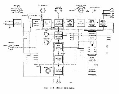
TECHNICAL DESCRIPTION
General
Circuit Summary
MAINTENANCE NOTES
Removal of Case
Access to printed circuit Boards
A. C. Mains Input Ranges
Fault Finding
COMPONENT LISTS
CIRCUIT DIAGRAMS
DECIBEL CONVERSION TABLES
SUPPLEMENT
Operational Summary Card
|
Manual
Circuit and
Operation Instructions
available
Details Below
As a Download
Click Here
|
TF2330 Marconi Wave
Analyser
Manuals are Available Worldwide as a
Download.
The manual contains 53 pages including Circuits
Component lists and Layouts
Manual
54 A4 pages worldwide
( For all Payment Options )
( Please Click the Payment Links Below ) |
|
We do all we can to provide
the very best that is available for you.
But in the unlikely event that any data should not be as you expected.
A refund is always available. Kind Regards Allen and Alanna. |
|