|
Marconi FM AM Signal
Generator
TF995A/5 TF 995A/5 Close to
TF995B TF995B/2
TF995B/5 TF 995B
TF 995B/2 TF 995B/5
|
|
Circuit Diagram, Service
Manual, Service
Information, Schematic Diagrams and Manuals |
|
For Repairing, Restoration and
Servicing of Vintage and Modern Electronic Equipment |
|
Full Manual with Circuits
available
Details Below
As a Download
Click Here
|
|
Circuits
& Manuals
Military,
Radio, TV,
Amateur & Marine
World Wide Service
For
Lists Click Here
|
|
Use R/H scroll Bar
More information
below
Radio's For Sale
Click Here
Military and
Broadcast
Radio Ads Click
Here |
|
Military Radio Home
Click
Here If no Index to the left
|
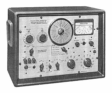
Marconi F.M./A.M. Signal Generator TF 995A/5
Frequency range of 1.5 to 220 Mc/s in five bands.
Its output can be un-modulated, frequency modulated, or amplitude modulated; if required, both frequency
and amplitude modulation can be applied simultaneously.
The modulation is obtained from either an internal 3-frequency oscillator, or an external source.
The open-circuit output voltage is variable by means of resistive step attenuators from 1
uV to 100 mV at 52 ohms and 1 uV to 200 mV at 75 ohms.
A plug-in 20-db Attenuator Pad, available as an optional accessory extends the range down to 0.1 uV at both impedances.
The high-discrimination tuning required for testing narrow-band systems is facilitated by the inclusion of a fine tuning control.
In addition, small known changes in carrier frequency can be made by means of two directly calibrated incremental
frequency controls.
One of these controls gives a stepped adjustment while the other allows continuous interpolation between steps.
On the two highest bands, the stepped control provides shifts of 20 and 40 kc/s in either direction and the calibration marks on the continuous control are only 1 kc/s apart.
On the lower bands, the total shift is determined by a simple division of the reading on both dials.
A high degree of frequency stability has been achieved by use of temperature
compensating components; after warm up, drift is less than 400 c/s per minute at a carrier frequency of 200 Mc/s.
The inclusion of a CARRIER on/off switch makes it possible for the Generator output to be temporarily interrupted
without affecting the output impedance; this facilitates a number of two signal receiver tests such as intermodulation and blocking which involves the simultaneous use of two signal generators.
Spurious f.m. due to hum is less than 25 c/s deviation, and the
low, level of noise modulation makes the TF 995A/5 fully suitable for applications such as adjacent
channel testing on receiver systems using a channel separation of 25 kc/s or less.
|
|
|
Full Manual with Circuits
available
Details Below
As a Download
Click Here
|
| The Information Consists
of the
Following
The Manual contains all circuits for the : -
Marconi FM AM Signal
Generator TF995A/5
Close also to the : -
TF995B TF995B/2 TF 995A/5 TF 995B
& TF 995B/2.
All 1960 vintage.
GENERAL
OPERATION
INSTALLATION
SWITCHING ON AND WARMING UP
TUNING
General tuning
Crystal Calibrator and its use
Incremental Frequency Controls
Interpolating Dial
SETTING UP FOR C.W. OR MODULATED OUTPUT
Continuous Wave
Amplitude Modulation
Frequency Modulation
Simultaneous A.M. and F.M.
R. F. OUTPUT ARRANGEMENTS
Outputs from 1 uV to 100 mV at 52 and 75 ohms
Outputs from 2 uV to 200 mV at 75 ohms only
Outputs from 0.1 uV to 10 mV at 52 and 75 ohms
Output in terms of voltage developed across external load
SYNCHRONIZING SIGNAL
TECHNICAL DESCRIPTION
R.F. CIRCUITS
MODULATION SYSTEMS
MONITORING ARRANGEMENTS
POWER UNIT
MAINTENANCE
ACCESS TO COMPONENTS
Removal from Case
Removal of R.F. Unit Cover
Removal of Monitor Diode (X2) Cover
MAINS INPUT CONNECTIONS
WORKING VOLTAGES
Power Supply Voltages
Valve Electrode Voltages
DRAWINGS
CIRCUIT DIAGRAM
BLOCK SCHEMATIC DIAGRAM
APPENDIX
DECIBEL CONVERSION TABLE *
Note Marconi did not include layouts in this manual *
|
Full Manual with Circuits
available
Details Below
As a Download
Click Here
|
If your model is the
TF995A/5 it will have a valve line up as below : -
Six; Type 6AK5, Pentodes.
One: Type 6AK6, Pentode.
One: Type 6AL5, Double Diode.
One: Type 6AU6, Pentode.
One: Type EF86, Pentode.
Two: Type 12AT7, Double Triodes.
One: Type 5Z4G Full Wave Rectifier.
One: Type OA2, Voltage Stabilizer.
One: Type 5651, Voltage Stabilizer.
|
If your model is the TF995A it
will have a valve line up as below : -
If it is the TF995A/1 it has
an extra valve a 12AT7 double triode.
Six: Type EF95 Pentodes.
Two: Type 6AK6 Pentodes.
One: Type 6AU6 Pentode
One: Type QS15O/15 Voltage Stabilizer.
One: Type 5Z4G Full Wave Rectifier,
One: Type D77 Double Diode.
|
Marconi
FM AM Signal
Generator TF995A/5 TF 995A/5
Close also to the TF995B
TF995B/2 TF995B/5
TF 995B
& TF 995B/2 TF 995B/5.
All 1960 vintage.
Manuals are Available Worldwide as a
Download.
For the TF995A an earlier 1954 model or the
TF995A/1 1955 Click Here
The Manual Contains 50 pages including
the circuit.
Manual 50 A4 pages worldwide
( For all Payment Options )
( Please Click the Payment Links Below )
|
|
We do all we can to provide
the very best that is available for you.
But in the unlikely event that any data should not be as you expected.
A refund is always available. Kind Regards Allen and Alanna. |
|