|
Marconi TF144H/4
TF144H/4R TF144H/4S
TF144H/6S Series II CT452
RF Signal Generators
TF-144H/4
TF-144H/4R TF-144H/4S
TF-144H/6S Series 2 CT-452 Download
This manual will also cover model
TF-144H/S.
Which may also have a CT452 label on it.
|
|
Circuit Diagram, Service
Manual, Service
Information, Schematic Diagrams and Manuals |
|
For Repairing, Restoration and
Servicing of Vintage and Modern Electronic Equipment |
|
Manual
with Circuits and
Layout images
Details Below
As a Download
Click Here
|
|
Circuits
& Manuals
Military,
Radio, TV,
Amateur & Marine
World Wide Service
For
Lists Click Here
|
|
Use R/H scroll Bar
More information
below
Radio's For Sale
Click Here
Military and
Broadcast
Radio Ads Click
Here |
|
Military Radio Home
Click
Here If no Index to the left
|
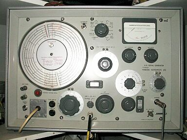
- Marconi Signal Generator
There are two versions in the
workshop : -
Standard version TF144H /4 - Service version (Military) TF144H /4S
(CT 452)
Frequency : - 10 kc/s to 72 Mc/s, in 12
bands.
Crystal Check : - 400 kc/s and 2 Mc/s
crystals selected automatically by band switch. Accuracy: +- 0 .005%.
Stability : - +- 0.002% in a 10 min
interval after warm up
Impedance : - 50 ohms
Calibrated Output : - 2uV to 2V e.m.f.
Low outputs down to 0.2uV using 20 dB pad TM 5573
Modulation : - Internal AM 400c/s and 1 kc/s switch selected. Depth 0 to 80%
Power Supply : - AC mains 200 to 250v
/100 to130v (40 to 60c/s) Consumption 80 watts.
Batteries : - LT- 6V, 2amps. HT-240v up
to 50mA
Weight : - TF144H /4 - 63lbs
- 28.6kg
TF144H /4S - 65 lbs -29.5kg
|
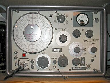
Standard version TF144H /4
|
|
Manual
with Circuits and
Layout images
Details Below
As a Download
Click Here
|
The Manual Consists
of the Following
GENERAL INFORMATION
Features
Standard and Service versions
Data Summary
Accessories
OPERATION
Installation.
Connections
Warming Up
Controls : Supply and Tuning
Controls : Modulation and Output
Quick Operational Check
C. W. Operation.
Use of Crystal Calibrator
Tuning Control Logging Scale
A. M. Operation
R. F Output Arrangements
Use of 20-db Attenuator Pad
Use of Dummy Aerial and D.C. Isolator
Direct Output
TECHNICAL DESCRIPTION
Circuit Summary
R. F. Oscillator
Range Switching
Main Tuning.
Incremental Tuning
Modulation Oscillator and Cathode Follower
A. L. C. and Modulation Amplifier
Crystal Calibrator
Crystal Calibrator Amplifier
Output Attenuators.
Direct Output.
Meter Monitoring
Power Supplies
MAINTENANCE
General
Mains Input Arrangement
Removal of Case - Access to Components
Static Voltages and Currents
Valve Failure and Replacement
Adjustment of Presets
Performance Checks
REPLACEABLE PARTS
CIRCUIT DIAGRAMS
DECIBEL CONVERSION TABLE
|
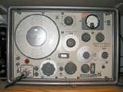
Service version (Military)
TF144H /4S
(CT 452)
|
|
Manual
with Circuits and
Layout images
Details Below
As a Download
Click Here
|
Marconi TF144H/4
TF144H/4R TF144H/4S TF144H/6S Series II CT452
RF Signal Generators
TF-144H/4
TF-144H/4R TF-144H/4S TF-144H/6S Series 2 CT-452
This manual will also cover
model TF-144H/S.
Which may also have a CT452 label on it.
It is comprehensive and gives all the relevant information to renovate a
Marconi TF144H Signal Generator.
I used this manual to renovate both of mine. |
Manual
with
Circuits and Layout images 69 pages
Manuals are Available Worldwide as a
Download.
Manual 69 A4 pages worldwide
( For all Payment Options )
( Please Click the Payment Links Below )
|
|
We do all we can to provide
the very best that is available for you.
But in the unlikely event that any data should not be as you expected.
A refund is always available. Kind Regards Allen and Alanna. |
|