|
Marconi Modulation Meter
TF2300A TF2300AR TF-2300A
TF-2300AR
|
|
Circuit Diagram, Service
Manual, Service
Information, Schematic Diagrams and Manuals |
|
For Repairing, Restoration and
Servicing of Vintage and Modern Electronic Equipment |
|
Manual
with Circuits and
Layout Images
Details Below
As a Download
Click Here
|
|
Circuits
& Manuals
Military,
Radio, TV,
Amateur & Marine
World Wide Service
For
Lists Click Here
|
|
Use R/H scroll Bar
More information
below
Radio's For Sale
Click Here
Military and
Broadcast
Radio Ads Click
Here |
|
Military Radio Home
Click
Here If no Index to the left
|
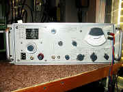
Marconi FM./AM.
Modulation Meter TF2300A
Marconi FM./AM. Modulation Meter TF2300AR
Primarily for measurement of FM deviation but it also measures AM depth.
Positive and negative FM deviation can be measured in ranges from 1.5 to
500 kHz full scale at modulation frequencies between 30 Hz and 3.4 kHz on
the 1.5 kHz deviation range and 30 Hz and 200 kHz on all other deviation
ranges.
AM depth can be measured up to 95% in a 30 Hz to 15 kHz modulation
bandwidth.
Either FM or AM can be measured in the presence of the other.
The unit can be operated from mains power or a nominal 24v battery.
Voltage regulation eliminates transformer tap changing except between 115v
and 230v ranges.
On battery the regulation compensates for battery
voltage variations between 21.5 and 30v.
Transistorized circuits consuming
little current give reasonable length of operation on battery for mobile
purposes.
Unit weighs 30 lbs-13.6kg. |
|
|
Manual
with Circuits and
Layout Images
Details Below
As a Download
Click Here
|
The Manual Consists
of the Following
GENERAL INFORMATION
Introduction
Data summary
Accessories
OPERATION
Installation
Power supply
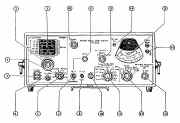
Controls
Preparation for use
Measuring F.M. deviation
Measuring A.M. depth
Measuring F.M. on A.M.
Measuring A.M. on F.M.
Noise measurements
Oscillator arrangements
Measurement in 1 to 2 MHz range
Asymmetric modulation and carrier shift
Use of L.F. output terminals
Use of I.F. output socket
Crystal selection
F. M. stereo measurements
Phase modulation and telemetry deviation
Stray fields
Decibel conversion tables
TECHNICAL DESCRIPTION
System operation
Power unit
Mixer
Local oscillator
I.F. amplifier
Limiter
Discriminator
Calibrator
Low-pass filters
1st L.F. amplifier
2nd L.F. amplifier
Peak reading meter
A.M. detector
Between-units circuitry on chassis
MAINTENANCE
Introduction
Access and layout
Performance checks
Component layout illustrations
Cleaning and lubricating
REPAIR
Introduction
Fault location
Waveforms
Realignment
Replacement of sub-assemblies
Replacement of components
REPLACEABLE PARTS
Introduction
CIRCUIT DIAGRAMS
Circuit notes
Inter-unit wiring
Mixer, oscillator and I.F. amplifier
Limiter, discriminator and 1st L.F.. amplifier
2nd L.F. amplifier and voltmeter
A. M. detector and calibrator
Power supply unit |
|
|
Manual
with Circuits and
Layout Images
Details Below
As a Download
Click Here
|
Marconi
TF2300A TF2300AR
TF-2300A TF-2300AR Modulation Meter
Manuals are Available Worldwide as a
Download.Manual with Circuits and
Layout images 76 pages
Manual 76 A4 pages worldwide
( For all Payment Options )
( Please Click the Payment Links Below )
|
|
We do all we can to provide
the very best that is available for you.
But in the unlikely event that any data should not be as you expected.
A refund is always available. Kind Regards Allen and Alanna. |
|