|
Marconi Carrier
Deviation Meter TF 791C
|
|
Circuit Diagram, Service
Manual, Service
Information, Schematic Diagrams and Manuals |
|
For Repairing, Restoration and
Servicing of Vintage and Modern Electronic Equipment |
|
Manual
Circuit and
Operation Instructions
available
Details Below
As a Download
Click Here
|
|
Circuits
& Manuals
Military,
Radio, TV,
Amateur & Marine
World Wide Service
For
Lists Click Here
|
|
Use R/H scroll Bar
More information
below
Radio's For Sale
Click Here
Military and
Broadcast
Radio Ads Click
Here |
|
Military Radio Home
Click
Here If no Index to the left
|
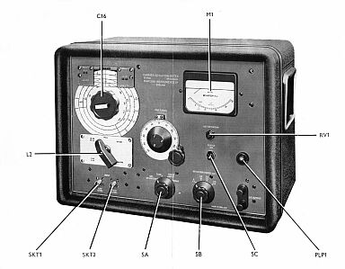
| Marconi Carrier
Deviation Meter TF 791C
The TF 791C is a direct reading instrument having deviation measurement ranges of 5, 25, 75, and 125 kc/s full-scale.
The modulation-frequency range extends from 50 c/s to 35 kc/s.
The calibrated carrier-frequency range is 4 to 270 Mc/ s but, by the use of local oscillator harmonics, the instrument can be employed up to 540 Mc/s.
Deviation is read on a panel meter, in addition front panel terminals fed from a separate output stage
provide an outlet for the products of
demodulation.
They permit external aural or visual monitoring of the modulation of the signal under test.
High measurement accuracy is ensured by the provision of built in facilities for generating a crystal controlled signal, which serves as a deviation standard.
|
|
| The Manual Contains the
Following DESCRIPTION
GENERAL
DESIGN DETAILS
OPERATION
INSTALLATION
SWITCHING ON AND WARMING UP
SETTING UP DEVIATION METER AND MAKING A MEASUREMENT
Standardizing Deviation Scale
Applying Signal to be Measured
Tuning, Checking Input Level, and Reading Deviation
ASYMMETRIC MODULATION AND CARRIER SHIFT.
MEASUREMENTS ABOVE 270 Mc/s
SETTING UP DEVIATION METER AT SUPPLY FREQUENCIES OTHER THAN 50 c/s
USE OF L.F. OUTPUT TERMINALS
OPERATIONAL SUMMARY
MAINTENANCE
GENERAL
FUSES
REMOVAL OF CASE
MAINS INPUT ARRANGEMENTS
For Supply Voltages from 180 to 250 volts
For Supply Voltages from 100 to 150 volts
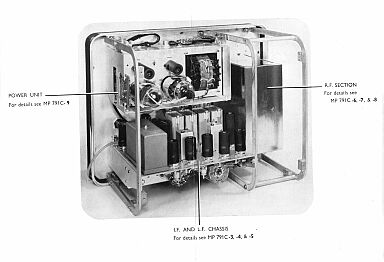
ACCESS TO SUB -ASSEMBLIES
Power Unit
Integrating Filter
Local Oscillator and Mixer
Coil Turret
WORKING VOLTAGES
REPLACEMENT OF VALVES AND CRYSTALS
PRESET AND SPECIALLY SELECTED COMPONENTS
SCHEDULE OF TESTS
Apparatus Required
Power Unit
I.F, Amplifier and Limiter
Counter Linearity
Meter Zero
L. F. Amplifier and Valve Voltmeter
Tuning Dial Calibration
Oscillator Output
Minimum B. F. Input Leval
I.F. Traps
Overall Hum and Noise
Deviation Reading
DIAGRAM IN TEXT
MAINS INPUT CONNECTIONS
APPENDICES
VALVE REPLACEMENT DATA
COMPONENT LAYOUT ILLUSTRATIONS.
SPARES ORDERING SCHEDULE WITH CIRCUIT REFERENCES
BLOCK SCHEMATIC DIAGRAM
CIRCUIT DIAGRAM |

|
|
Manual
Circuit and
Operation Instructions
available
Details Below
As a Download
Click Here
|
Marconi Carrier
Deviation Meter TF 791C
Manuals are Available Worldwide as a
Download.
Manual containing 74 pages including the Circuit with Component
lists and layouts.
Manual 74 A4 pages worldwide
( For all Payment Options )
( Please Click the Payment Links Below )
|
|
We do all we can to provide
the very best that is available for you.
But in the unlikely event that any data should not be as you expected.
A refund is always available. Kind Regards Allen and Alanna. |
|