|
KW 202 SSB
Receiver
Communication Receiver |
|
Circuit Diagram, Service
Manual, Service
Information, Schematic Diagrams and Manuals |
|
For Repairing, Restoration and
Servicing of Vintage and Modern Electronic Equipment |
|
Manual
Circuit and
Operation Instructions
available
Details Below
As aDownload
Click Here
|
|
Circuits
& Manuals
Military,
Radio, TV,
Amateur & Marine
World Wide Service
For
Lists Click Here
|
|
Use R/H scroll Bar
More information
below
Radio's For Sale
Click Here
Military and
Broadcast
Radio Ads Click
Here |
|
Military Radio Home
Click
Here If no Index to the left
|
KW 202 SSB
Receiver
GENERAL DESCRIPTION AND SPECIFICATION
Introduction
The K.W. 202 Receiver has been designed for optimum performance on SINGLE SIDEBAND SUPPRESSED CARRIER, with excellent results on C.W. and A.M.
It operates on
all Amateur Bands between 1.8 MHz and 30 MHz.
The Receiver employs thirteen valves in a double-conversion superhet circuit, plus 12 diodes arid one transistor.
The K.W. 202 has a built-in power unit operating from a 105 - 120, 210 -
240v AC 45-65 Hz AC Supply.
A two speed V.F.0 drive is used to rotate the scale which is calibrated 0-500 KHz, and can be re-set for optimum read out accuracy.
A plug-in CRYSTAL CALIBRATOR provides marker signals every 100 KHz for checking the dial calibration accuracy; (This is available as an optional extra).
A built-in
Q-MULTIPLIER improves the selectivity for CW operation, and has a NOTCH facility for rejecting unwanted
heterodynes and certain interfering signals.
Specification
BANDS COVERED
1.8 — 2.3 MHz
3.5 — 4.0 MHz
7.0 — 7.5 MHz
14.0 —14.5 MHz
21.0 — 21.5 MHz
28.0 — 28.5 MHz
28.5 — 29.0 MHz
29.0 — 29.5 MHz
29.5 — 30.0 MHz.
STABILITY
With constant input voltage to Receiver better than 200 Hz after warm-up period
of 30 minutes.
POWER REQUIREMENTS
105 - 120, or 210 - 240v AC
40 - 65 Hz 80 Watts
RECEPTION MODES
SSB (either sideband selectable) AM
CW
ANTENNA INPUT IMPEDANCE
52/75 ohms. V.H.F. S0239 Socket.
SENSITIVITY
Better than 1 uV for 500 mW output.
SIGNAL-PLUS-NOISE TO
NOISE RATIO
1 V for 20 dB
|
|
| The Manual Contains the
Following
SPECIFICATION 1
GENERAL DESCRIPTION AND SPECIFICATION
Introduction
Specification
Valve and Semi-Conductor Complement
SECTION 2
CIRCUIT DECRIPTI0N
RF and mixer Circuits
Oscillator Circuits
IF and Detector Circuits
Q Multiplier
S Meter
Audio Circuits
Wave change Switch
Pre-Selector
Power Supply Unit
SECTION 3
INSTALLATION
Unpacking
Station Installation
Antenna
Loudspeaker
“Anti-Trip” and “Side Tone”
Initial Checks
SECTION 4
OPERATION
General
SSB Operation
A.M. Reception
C.W. Reception
Q Multiplier
Calibration
S Meter
Muting
SECTION 5
SERVICE INSTRUCTIONS
General
Trouble Analysis
Signal Tracing Procedures
Voltage and Resistance Measurements
Alignment Procedure
Pre-Selector 3.5 MHz Band
IF Trap
455 KHZ IF Transformers
V.I.F. Transformers
‘S’ Meter Calibration
V.F.O. Calibration
U.L.S.B. Switching
Pre-Selector 29.5 MHz Band
Pre-Selector 21.0 MHz Band
Pre-Selector 14.0 MHz Band
Pre-Selector 7.0 MHz Band
Pre-Selector 1.8 MHz Band
Pre-Selector Coil Cores
Field Alignment
SECTION 6
TABLES AND ILLUSTRATIONS
Voltage and Resistance Measurements
Signal Levels
Station Installation
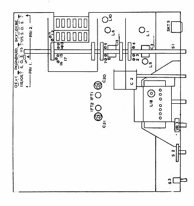
location of Adjustments under Chassis
Location of Valves and Crystals
Circuit Diagram
|
Manual
Circuit and
Operation Instructions
available
Details Below
As a Download
Click Here
|
KW 202
SSB
Receiver
Manuals are Available Worldwide as a Download.
Manual containing 34 pages including the Circuit with Component
values.
Manual 34 A4 pages worldwide
( For all Payment Options )
( Please Click the Payment Links Below ) |
|
We do all we can to provide
the very best that is available for you.
But in the unlikely event that any data should not be as you expected.
A refund is always available. Kind Regards Allen and Alanna. |
|