|
Class D Wavemeter No1 Mk
1 Mk 2 Mk 2*
Frequency Meter Wave Meter
|
|
Circuit Diagram, Service
Manual, Service
Information, Schematic Diagrams and Manuals |
|
For Repairing, Restoration and
Servicing of Vintage and Modern Electronic Equipment |
|
Manual
Circuit and
Operation Instructions
available
Details Below
As a Download
Click Here
|
|
Circuits
& Manuals
Military,
Radio, TV,
Amateur & Marine
World Wide Service
For
Lists Click Here
|
|
Use R/H scroll Bar
More information
below
Radio's For Sale
Click Here
Military and
Broadcast
Radio Ads Click
Here |
|
Military Radio Home
Click
Here If no Index to the left
|
Class D Wavemeter No1
Mk
1 Mk 2 Mk 2*
Wave Meter Class D. No. I
MK I, MK II and MK 11*
GENERAL DESCRIPTION.
Purpose and facilities.
The Wavemeter Class D. No. 1, Mk. I, Mk, II and Mk. 11*
Is a portable heterodyne wavemeter similar to the instrument previously known as Corrector Frequency.
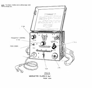
NOTE
The Wavemeter Class D. No. 1, Mk. I is the original Corrector Frequency with minor circuit changes.
It has a detachable lid.
The Wavemeter Class D. No. 1, Mk. II
Is the same as the Mk. I instrument except for minor circuit changes. It has a hinged lid.
The Wavemeter Class D. No. 1, Mk. 11*
Is the same as the Mk. II instrument except for component changes.
The Wavemeter is designed for adjusting senders and receivers to particular frequencies, for checking frequency calibration of these sets, and for determining the frequency of a received signal.
The accuracy of the wavemeter can be expected to be within + or - 2 kc/s. over ranges 1 and 2.
The frequency band covered is 1900 kc/s to 8000 kc/s (158—37.5 m.) in two ranges
: -
1900 kc/s - 4000 kc/s and 4000 kc/s - 8000 kc/s.
The instrument also provides check frequencies, spaced apart by 1
mc/s (1000 kcs), up to 25 mc/s (25,000 kc/s). These check frequencies are used for verifying gross errors of calibration.
WEIGHTS AND DIMENSIONS.
Weight. 11 lb Width. 8 1/2 in Height. 7 1/2 in Depth. 6 1/4 in
3. Power Supply.
The power supply for the wavemeter is normally a 6-volt accumulator external to the instrument. A Clip Battery Special No. 1 is also issued with the wavemeter which enables 6 volts to be tapped from a higher voltage accumulator.
This provides filament heating for the valve and dial lamp and also supplies a vibrator which is housed in the instrument for H.T. through a bridge-connected metal rectifier system.
The total current consumption is
1.1 amp. at 6 volts.
|
|
|
Manual
Circuit and
Operation Instructions
available
Details Below
As a Download
Click Here
|
| The Manual Contains the
Following :-
CHAPTER I GENERAL DESCRIPTION.
Purpose and facilities
Weights and dimensions
Table I - Weights and dimensions
Power supply
Technical description
(1) Principle of operation
(2) The wavemeter circuit
(3) The power supply circuit
(4) Construction
CHAPTER 2 WORKING INSTRUCTIONS.
Preliminary
To set the wavemeter Class D. No. 1 to a given frequency
To couple the wavemeter to a sender for receiver aerial
To set a sender to a given frequency
To set a receiver to a given frequency
Netting
To determine the frequency of a received signal
Preliminary check on calibration of receiver or sender
CHAPTER 3 MAINTENANCE.
Scale alignment
To adjust the grid condenser C13A
To re-set the crystal oscillator output resistance
control
APPENDIX I.
List of main components
DIAGRAMS.
Wavemeter Class D. No. 1, Circuit diagram.
Simplified diagram of wavemeter Class D. No. 1.
Valve connections.
Crystal connections.
Vibrator connections.
Wavemeter Class D. No. 1, diagram showing principle of operation.
Wavemeter Class D. No. 1, Front view.
Wavemeter Class D. No. 1, Internal view from above.
Wavemeter Class D. No. 1, Internal view from below. |
Class D Wavemeter No1
Mk
1 Mk 2 Mk 2*
Manuals are Available Worldwide as a
Download.
Working
Instructions 33 pages including the Circuit with Component
lists and layouts.
Manual 33 A4 pages worldwide
( For all Payment Options )
( Please Click the Payment Links Below ) |
|
We do all we can to provide
the very best that is available for you.
But in the unlikely event that any data should not be as you expected.
A refund is always available. Kind Regards Allen and Alanna. |
|