| The Information Consists
of the
Following :-
GENERAL DESCRIPTION.
Purpose of Handbook.
Purpose of Equipment
General Principles of Operation
Equipment Supplied
Equipment Required But Not Supplied
General Electrical Characteristics
Description of Major Units
Interchangeability of AN/ARC-5 and ATA Components
Manufacturers and Contract Numbers
INSTALLATION AND ADJUSTMENT
Unpacking and Inspecting the Equipment
Pre-Installation Tests
Installation
Adjustments
OPERATION
Operating Controls
Remote Control Operation of Receivers
Lock-Tuned Operation of Receivers
Operation of Crystal Frequency Generator 0-4/ARC-5
Operation of the Transmitters
Limiting Conditions of Operation
Operating Precautions
Adjustment Precautions
Emergency Operation
THEORY OF OPERATION
Introduction
Radio Receivers R-23/ARC-5, R-24/ARC-5, R-25/ARC-5, R-26/ARC-5, and R-27/ARC-5
Radio Receivers R-23A/ARC-5 and R-148/ARC-5X
Dynamotor *DY-2A/ARR-2
Dynamotor *DY-1/ARR-2X
Dynamotor DY-2B/ARR-2
Adapters MX-19/ARC-5, MX-20/ARC-5, and MX-21/ARC-5
Radio Transmitters T-15/ARC-5, T-16/ARC-5, and T-17/ARCS
Radio Transmitters T-18/ARC-5, T-19/ARC-5, T-20/ARC-5, T-21/ARC-5, and T-22/ARC-5
Modulator MD-7/ARC-5 and Dynamotor DY-8/ARC-5
Antenna Loading Coil TN-6/ARC-5
Antenna Relay Unit RE-2/ARC-5
Control Unit C-24/ARC-5
Control Unit C-25/ARC-5
Control Unit C-26/ARC-5
Control Unit C-27/ARC-5
Control Unit C-29/ARC-5
Control Unit C-30A/ARC-5
Control Unit C-38/ARC-5
Control Units C-39/ARC-5 and C-48/ARC-5
Control Panel C-125/ARC-5
Radio Set Control C-744/ARC-5
Dials ID-25/ARC.5, ID-26/ARC-5, ID-27/ARC-5, ID-28/ARC-5, and ID-29/ARC-5
Racks *MT-7A/ARR-2, MT-63/ARC-5, MT-65/ARC-5, and MT-67/ARC-5
Rack MT.411/ARC-5X
Racks MT-69/ARC-5, MT-71/ARC-5, MT-73/ARC-5, and MT-75/ARC-5
Junction Box J-17/ARC-5
Junction Box J-17A/ARC-5
Junction Box J-28/ARC.5
Junction Box J-34/ARC.5
Jack Boxes J.16/ARC-5 and J-22/ARC-5
Jack Box J22A/ARC-5
Jack Box J-22B/ARC-5
MAINTENANCE
Introduction
Preflight Inspection
Monthly Inspection
Removal and Disassembly of Radio Receivers.
Removal and Disassembly of Radio Transmitters
Trouble Shooting the Radio Receivers
Radio Receiver R-F and I-F Alignment
Sense and Preferred Setting of All Trimmer Capacitors
Maintenance of Radio Receiver Dynamotors
Trouble Shooting the Radio Transmitters
Radio Transmitter Alignment Procedure
Maintenance of Radio Transmitter Dynamotors
SUPPLEMENTARY DATA
Functional Tube and Lamp Complement
Supplementary Data
TABLE OF REPLACEABLE PARTS
General
Ordering of Spare Parts
Manufacturers and Contract Numbers
List of Manufacturers
Resistor Color Code
Capacitor Color Codes
Wire and Coil Color Codes
Table of Replaceable Parts
DIAGRAMS
INDEX
LIST OF ILLUSTRATIONS
Model AN/ARC-5 Aircraft Radio Equipment, Radio Receivers, Dynamotors, Racks, Mounting Bases, and Adapters
Model AN/ARC-5 Aircraft Radio Equipment, Radio Transmitters, Racks, and Mounting Bases
Model AN/ARC-5 Aircraft Radio Equipment, Modulator with Dynamotor and Mounting Base, and Antenna Relay Unit with Mounting Base
Model AN/ARC-5 Aircraft Radio Equipment, Control Units Model AN/ARC-5 Aircraft Radio Equipment, Junction Boxes, Jack Boxes, Adapters, Knobs, and Coupling
Model AN/ARC-5 Aircraft Radio Equipment, Typical ME Transmitter and Antenna Loading Coil
Control Unit C-24/ARC-5, Operating Controls
Control Unit C-25/ARC-5, Operating Controls
Control Unit C-26/ARC-S, Operating Controls
Control Unit C.27/ARC-5, Operating Controls
Control Unit C-29/ARC-5, Operating Controls
Control Unit C-30A/ARC-5, Operating Controls
Control Unit C-38/ARC-5, Operating Controls
Control Units C-39/ARC-5 and C-48/ARC-5, Operating Controls
Control Panel C-125/ARC-5, Operating Controls
Radio Set Control C-744/ARC-5, Operating Controls
Radio Transmitter, Functional Schematic Diagram
Radio Transmitting Audio-Frequency Circuits, Schematic Diagram
Radio Transmitter, Low-Voltage D-C Circuits, Schematic Diagram
Radio Transmitter, High-Voltage D-C Circuits, Schematic Diagram
Radio Receiver, Terminal Voltage Measurements
I-f Coupling Unit Assemblies, Top Views
Radio Transmitter, Terminal Voltage Measurements
Modulator, Terminal Voltage Measurements
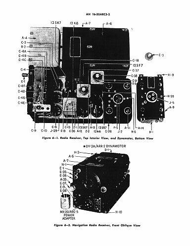
Radio Receiver, Top Interior View, and Dynamotor, Bottom View
Navigation Radio Receiver, Front Oblique View
Navigation Radio Receiver, Bottom Interior View
Communication Radio Receiver, Front Oblique View
Communication Radio Receiver, Bottom Interior View
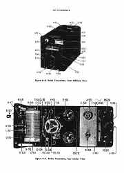
Radio Transmitter, Front Oblique View
Radio Transmitter, Top Interior View
Radio Transmitter, Bottom Interior View
Modulator MD-7/ARC-5, Top View, Shield and Dynamotor Removed
Modulator MD-7/ARC-5, Bottom Interior View
Dynamotor DY.8/ARC-5, Bottom View
Control Unit C-29/ARC-5, Front and Rear Views
Control Unit C-29/ARC5, Rear Interior View
Radio Set Control C-744/ARC-5, Front View
Radio Set Control C-744/ARC-5, Interior View
Racks MT-63/ARC-5 (2-Receiver) and MT-65/ARC-5 (3-Receiver), Front and Rear Interior Views
Rack MT-69/ARC-5, Front and Rear Interior Views
Rack MT-71/ARC-5, Front and Rear Interior Views
Antenna Relay Unit RE-2/ARC-5, Front and Bottom Interior Views
Crystal Frequency Generator 0-4/ARC-5
Resistor Color Code
Capacitor Color Codes
Radio Receiver and Transmitter Wire and Coil Color Codes Radio Receivers R-23/ARC-5 and R-24/ARC-5, with * Dynamotor DY-2A/ARR-2, Schematic Diagram
Radio Receivers R-25/ARC-5, R-26/ARC-5, and R-27/ARC-5 with Dynamotor *DY-2A/ARR-2, Schematic Diagram
Radio Receivers R.23A/ARC.5 and R.148/ARC-5X, Schematic Diagram
Audio, Power, and Remote Control Adapters, Schematic Diagrams Radio Transmitting Equipment, Schematic and External Wiring Diagram
Radio Transmitter T-l5/ARC-5, Schematic Diagram
Radio Transmitter T-16/ARC-5, Schematic Diagram
Radio Transmitter T-17/ARC-5, Schematic Diagram
Radio Transmitters T-18/ARC-5, T-19/ARC-5, T-20/ARC-5, T-21/ARC-5, T-22/ARC-5, Schematic Diagrams
Control Units C-24/ARC-5, C-26/ARC-5, and C-27/ARC-5, Schematic Diagrams
Control Units C-30A/ARC-5 and C-38/ARC-5, Schematic Diagrams
Control Units C-39/ARC.5 and C-48/ARC-5, Schematic Diagrams.
Control Units C-125/ARC-5 and C-744/ARC-5, Schematic Diagrams
Rack MT-65/ARC-5, Schematic Diagram
Junction Boxes J-17/ARC-5 and J-l7A/ARC-5, Schematic Diagrams
Junction Boxes J-28/ARC-5 and J-34/ARC.5, Schematic Diagrams.
Jack Boxes J-16/ARC-5, J.22/ARC-5, J-22A/ARC-5, and J-22B/ARC-5, Schematic Diagrams
Antenna Loading Coil TN-6/ARC-5, Schematic and Wiring Diagrams
Crystal Frequency Generator 0-4/ARC-S. Schematic and Wiring Diagrams
Radio Receiver R-23/ARC-5, Wiring Diagram
Radio Receiver R-23A/ARC-5, Wiring Diagram
Radio Receiver R-148/ARC-SX, Wiring Diagram
Radio Receiver R-24/ARC-5, Wiring Diagram
Radio Receiver R-25/ARC-5, Wiring Diagram
Radio Receiver R-26/ARC-5, Wiring Diagram
Radio Receiver R-27/ARC-5, Wiring Diagram
Radio Transmitter T-l 5/ARC-5, Wiring Diagram
Radio Transmitter T-16/ARC-5, Wiring Diagram
Radio Transmitter T-17/ARC-5, Wiring Diagram
Radio Transmitters T-18/ARC-5, T-19/ARC-5, T-20/ARC-5, T-21/ARC-5, T-22/ARC-5, Wiring Diagram
Modulator MD-7/ARC-5, Wiring Diagram Control Units C-24/ARC-5, C-26/ARC-5, C-27/ARC-5, Wiring Diagrams
Control Unit C-29/ARC-5, Wiring Diagram
Control Unit C-30A/ARC-5, Wiring Diagram
Control Unit C-38/ARC-5, Wiring Diagram
Control Unit C-39/ARC-5, Wiring Diagram
Control Unit C-48/ARC-5, Wiring Diagram
Control Units C-125/ARC-5 and C-744/ARC.5, Wiring Diagrams
Racks MT-7A/ARR-2 and MT-411/ARC-5X, Wiring Diagram
Rack MT-63/ARC-5, Wiring Diagram
Rack MT-67/ARC-5, Wiring Diagram
Rack MT-65/ARC-5, Wiring Diagram
Rack MT-69/ARC-5, Wiring Diagram
Rack MT-71/ARC-5, Wiring Diagram
Rack MT-73/ARC-5, Wiring Diagram
Rack MT.75/ARC-5, Wiring Diagram
Dynamotors *DY-1/ARR-2x, *DY-2A/ARR-2, and DY-2B/ARR-2, Wiring Diagram
Dynamotor DY-8/ARC-5, Wiring Diagram
Audio, Power, and Remote Control Adapters, Wiring Diagrams
Junction Box J-17/ARC-5, Wiring Diagram
Junction Box J-17A/ARC-5, Wiring Diagram
Junction Boxes J-28/ARC-5 and J-34/ARC-5, Wiring Diagram
Jack Boxes J-16/ARC-5, J-22/ARC-5, J-22A/ARC-5, and J-22B/ARC-5, Wiring Diagrams
Antenna Relay Unit RE-2/ARC-5, Wiring Diagram
Model AN/ARC-S Aircraft Radio Equipment, External Wiring
Diagrams (Sheet 1 of 9)
Model AN/ARC-5 Aircraft Radio Equipment, External Wiring
Diagrams (Sheet 2 of 9)
Model AN/ARC-5 Aircraft Radio Equipment, External Wiring
Diagrams (Sheet 3 of 9)
Model AN/ARC-5 Aircraft Radio Equipment, External Wiring
Diagrams (Sheet 4 of 9)
Model AN/ARC-5 Aircraft Radio Equipment, External Wiring
Diagrams (Sheet 5 of 9)
Model AN/ARC.5 Aircraft Radio Equipment, External Wiring
Diagrams (Sheet 6 of 9)
Model AN/ARC-5 Aircraft Radio Equipment, External Wiring
Diagrams (Sheet 7 of 9)
Model AN/ARC-5 Aircraft Radio Equipment, External Wiring
Diagrams (Sheet 8 of 9)
Model AN/ARC-5 Aircraft Radio Equipment, External Wiring
Diagrams (Sheet 9 of 9)
Antenna Loading Coil TN-6/ARC-5, Transmitter Antenna
Connections and Cabling
Model AN/ARC-5 Aircraft Radio Receiving Equipment,
Component Installation Dimensions and Weights
Model AN/ARC-5 Aircraft Radio Transmitting Equipment,
Component Installation Dimensions and Weights
Control Units, Junction Boxes, and Jack Boxes, Installation
Dimensions and Weights
Antenna Loading Coil TN-6/ARC-5, Installation Dimensions and
Weight
Cable Assemblies and Mechanical Linkage, Assembly and Fabrication Diagrams (Sheet 1 of 3)
Cable Assemblies and Mechanical Linkage, Assembly and Fabrication Diagrams (Sheet 2 of 3)
Cable Assemblies and Mechanical Linkage, Assembly and
Fabrication Diagrams (Sheet 3 of 3)
Dynamotor *DY-2A/ARR-2, Detail Parts and Cross-Section
Dynamotor DY-8/ARC-5, Detail Parts and Cross-Section
Radio Receiver R-23/ARC-5, 85 KC I-f Coupling Units, Assembly Diagrams
Radio Receiver R-23A/ARC-5 and R-148/ARC-5X, 85-KC I-f
Coupling Units, Assembly Diagrams
Radio Receivers 239-KC I-f Coupling Units, Assembly Diagrams
Radio Receivers 705-KC I-f Coupling Units, Assembly Diagrams
Radio Receivers 1415-KC I-f Coupling Units, Assembly Diagrams
Radio Receivers 2830-KC I-f Coupling Units, Assembly Diagrams
Test Set 7918 and 9558, AN/ARC-5 Bench Test Interconnection Diagrams and
Schematic Diagrams |
|