|
53 Set Transmitter
Wireless Sender
|
|
Circuit Diagram, Service
Manual, Service
Information, Schematic Diagrams and Manuals |
|
For Repairing, Restoration and
Servicing of Vintage and Modern Electronic Equipment |
|
Manual and
Circuit
available
Details Below
As a Download
Click Here
|
|
Circuits
& Manuals
Military,
Radio, TV,
Amateur & Marine
World Wide Service
For
Lists Click Here
|
|
Use R/H scroll Bar
More information
below
Radio's For Sale
Click Here
Military and
Broadcast
Radio Ads Click
Here |
|
Military Radio Home
Click
Here If no Index to the left
|
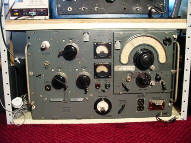
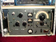
The 53 Set Transmitter
There is more to this HF transmitter
than I have, namely the modulator and power supply.
The unit pictured has
the PA stages with 3 large roller coasters and a couple of 813's.
The VFO
is the separate slide in unit with the large dial.
This one is in mint
condition never having been used, one day I shall find the other
bits, power it up and dim the lights in Mullion Cove.
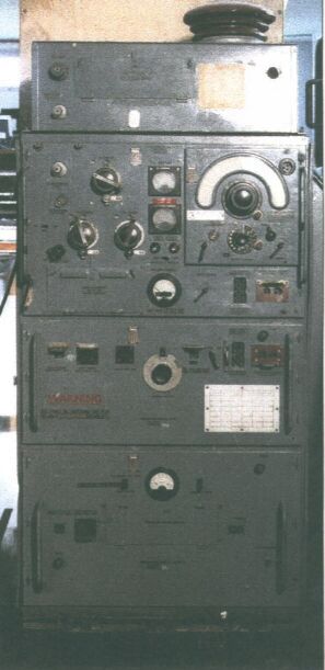
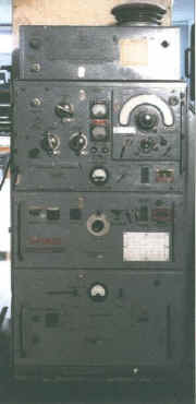
The complete transmitter should look
like the one below right, the unit on top I believe is the ATU.
All
other photographs are of my own equipment, but as I do not have a complete
set the image to the right is not mine |
|
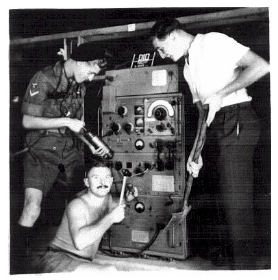
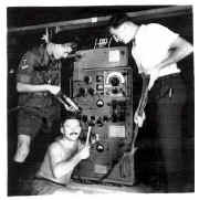
The photo to the right taken in the
1950s shows how not to service a 53 set, it was kindly supplied by Mr
Brian Goode.
Brian operated and serviced this radio transmitter as well as the 19 set
AR88 and others.
Bian is the good looking fellow on the left with
the fire extinguisher.
Update from Brian
Just for info. - The grease gun was a fire extinguisher and the other two were:- Sam Blake and 'Lofty' Manners.
Sam, who lived in Chorlton-cum-Hardy, Manchester, died a couple of years ago but I haven't any info on 'Lofty' Manners apart from the facts that he was a Nat. Serviceman and came from the West Country.
The three of us served in Gurkha Royal Signals (now the Queens Gurkha Signals) and the photoraph was taken in the transmitter site at Rasah Camp,
Seremban, Malaya.
The camp being the HQ of the 17th Gurkha Infantry Division. (1955).
|
|
| The Wireless Sender No 53 Manual Contains the
Following :-
GENERAL DESCRIPTION.
Purpose and facilities
Power output
Frequency band
Power supply
Aerials
Control
Receiver
Sender assembly
Brief circuit description
Weights and dimensions
TABLE I WEIGHTS AND DIMENSIONS.
OPERATION.
Preliminary
Setting up
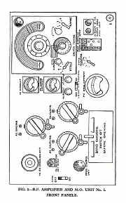
R.F. Amplifier and Master Oscillator
Modulator Unit No. 27
Power Supply Unit No. 26
Connecting up
TABLE II INTERCONNECTION OF UNITS.
To operate
Netting procedure
Notes
Opening up and prepare to net drill
Netting drill
Establishing communications
Closing down drill
Crystal control operation
MAINTENANCE.
Daily Maintenance
Weekly Maintenance
Details of components
Appendix I. Aerial Length Chart
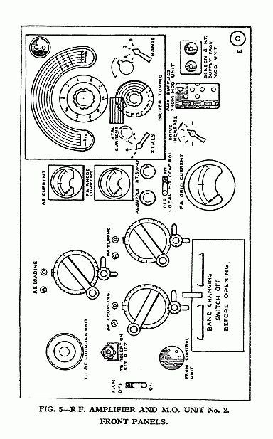
DIAGRAMS
Wireless Sender No. 53 mounted in racks mounting No. 12. Front view.
Wireless Sender No. 53 mounted in racks mounting No. 12. Rear view.
Power Supply Unit No. 26. Front panel.
Modulator Unit No. 27. Front panel.
R.F. Amplifier and Unit Master Oscillator No. 2. Front panels.
Power Supply Unit No. 26. Plan view.
Modulator Unit No. 27. Plan view.
R.F. Amplifier and Master Oscillator. Plan view.
Aerial Coupling Unit No. 2A. Plan view.
P.S.U. No. 26 Circuit Diagram
Modulator Unit No. 27. Circuit diagram.
R.F. Amp., M.O., and Aerial Coupling Unit No. 2A. Circuit diagram.
|
|
|
Manual and
Circuit
available
Details Below
As a Download
Click Here |
|
|
The 53 Set Wireless Sender Manual contains 36 A4 Pages
including Circuits Component lists and Layouts.
Manuals are Available Worldwide as a
Download.
Manual 36 A4 pages worldwide.
( For all Payment Options )
( Please Click the Payment Links Below ) |
|
We do all we can to provide
the very best that is available for you.
But in the unlikely event that any data should not be as you expected.
A refund is always available. Kind Regards Allen and Alanna. |
|