|
R1155 Receiver Lancaster Bomber
Receiver 1155
RX Radio Wireless Set Equipment 1155 Manual with
Circuit.
R1155B R1155C R1155D R1155E R1155F R1155L R1155M
|
|
Circuit Diagram, Service
Manual, Service
Information, Schematic Diagrams and Manuals |
|
For Repairing, Restoration and
Servicing of Vintage and Modern Electronic Equipment |
|
Manual and
Circuit
Plus Additional Articles
available as a Download
Details Below
Click Here
|
|
Circuits
& Manuals
Military,
Radio, TV,
Amateur & Marine
World Wide Service
For
Lists Click Here
|
|
Use R/H scroll Bar
More information
below
Radio's For Sale
Click Here
Military and
Broadcast
Radio Ads Click
Here |
|
Military Radio Home
Click
Here If no Index to the left
|
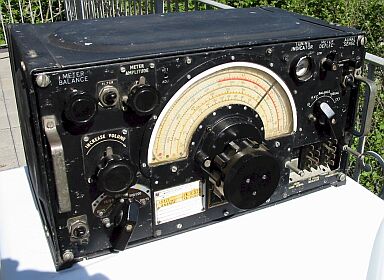
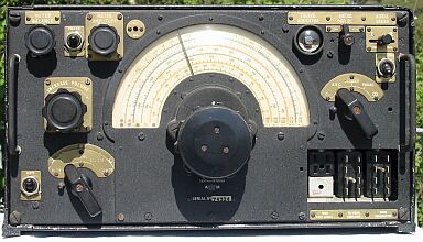
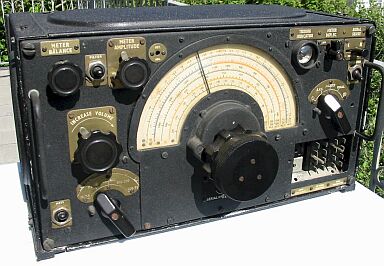
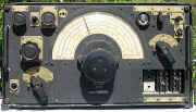
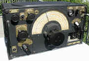
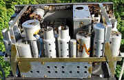
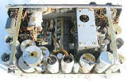
| Communications Receiver R1155 R1155B R1155C R1155D
R1155E R1155F R1155L R1155M The 1155 receiver was fitted into the
Lancaster bomber and marine craft such as motor torpedo boats, in
conjunction with the 1154 transmitter there purpose was communications and direction
finding.
There were several versions of them made covering different
frequencies.
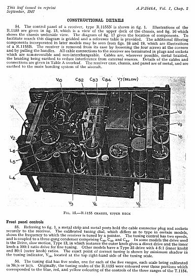
Coverage is from 18.5mc/s to 200kc/s with a gap between
600kc/s and 500kc/s.
The set draws 114watts from the power supply,
maximum power output 100 milliwatts 5000 ohms impedance.
The aircraft
version had an aluminium case for obvious reasons where as the marine
version had a steel case.
The weight of these units are 33 lbs
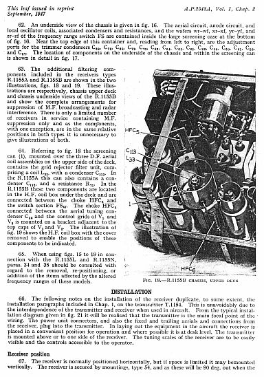
6oz.
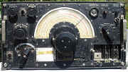
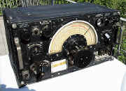
The sets photographed on the right are fully operational .
|
|
Additional information on the
Wireless Set 1155
Receiver
Kindly
supplied by Bob Fairman.
The Lancaster was not the only
aircraft in which this equipment was installed.
They were used extensively
in aircraft of all types in the RAF during and after WW2.
I used them
during the whole of my time in the RAF from 1949 to 1957 and they
continued in use for some years after that.
During that time rumour had it
that in a storage depot 'somewhere in England' there was a warehouse
stacked to the rafters with unused replacement sets, which explained why
they had not been superseded by radios of greater power which would have
been a boon to us ops on long range Transport Command. |
|
1155 Wireless Set
Receiver.
R1155 R1155B R1155C R1155D R1155E R1155F R1155L R1155M Manual and Circuit.
The 1155 Manual Contains the
Following :-
Introduction
Facilities
Power supplies
Aerials
General description
Frequency range switch
Master switch
Communications circuits R.1155 and R.1155D
Aerial connections.
R.F. amplifier stage
Frequency-changer stage
I.F. stages
Detector and output stages
Manual volume control
Automatic volume control
Beat frequency oscillator
Tuning indicator
Communications circuits, other versions - R.1155A, E, and M
1155B F C L and N
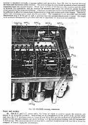
The direction-finding circuits
General principles
LF. oscillator for D.F. switching
Aerial switching
Visual indicator switching
Meter amplitude
The diode limiter valve
Visual indicator balancing circuit
Visual sense determination
Aural D.F.
Constructional details
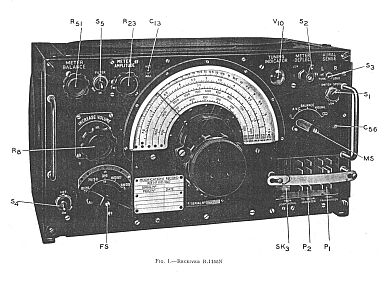
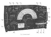
Front panel controls
Chassis layout
Installation
Receiver position
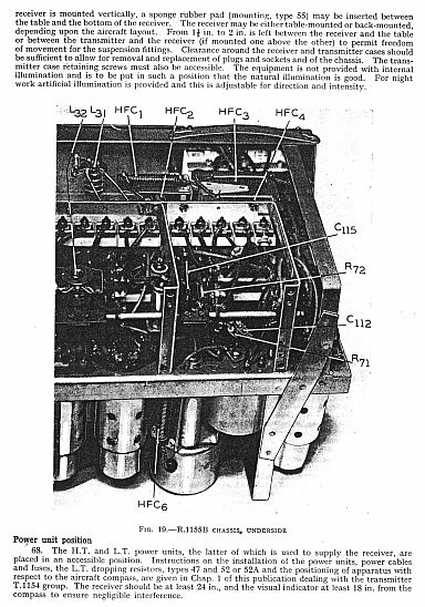
Power unit position
Aerial switch position
D.F. loop aerial and impedance matching
Fixed aerial input
The visual indicator, type I
Setting up the D.F. loop
Loop centre tap
Navigator-operated receivers
Power units Operation
Controls
Setting up heterodyne oscillator
Back-tuning
Normal communication
D.F. bearings using visual indicator
Homing using visual indicator
Aural DF.
Precautions and servicing
Ground testing
Starter trolley batteries
Visual indicator
Trouble location
Test apparatus
Valve data
Valve identification
Valve replacements
Removal of B.F.O. valve
Prevention of frequency drift
Alignment of incorrectly calibrated receivers
( Alignment is more fully covered in the
Articles )
( Please See further down the page or
Click Here )
Periodic inspections
Associated equipment
List of principal components
|
Manual and
Circuit
Plus Additional Articles
available as a Download
Details Below
Click Here
|
|
|
|
|
|
|
|
|
|
|
|
Manual and
Circuit
Plus Additional Articles
available as a Download
Details Below
Click Here
|
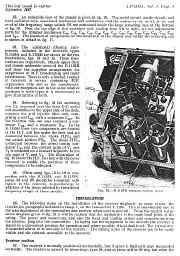
LIST OF ILLUSTRATIONS
Receiver R.1155N
Schematic diagram.
R1155 and R.1155D circuit diagram with modifications for
A E and M
R.1155B and R.1155F circuit diagram
R.1155L and R.1155N circuit diagram
Simplified communications circuit
I.F. response curve
A.F. filter characteristics
Biasing and feed arrangements
Input output characteristics
Simplified visual D.F. circuit
A.F. oscillator switching circuit
Visual indicator switching circuit
Simplified visual indicator switching circuit
Polar diagrams .
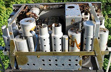
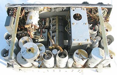
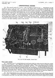
R.l155 chassis, upper deck.
R.1155 chassis, underside
Components location diagram .
R.1155B chassis, upper deck
R.1155B chassis, underside.
Valve connections.
Typical installation diagram
Plug, type 209
Trouble location chart - Communications circuits
Trouble location chart - D.F. Switching circuits
The impedance matching units types 12 13 and 15
Visual indicator, type I |
|
|
|
|
|
The Wireless Set 1155
Receiver
Manuals are Available Worldwide as a
Download
The Wireless Set
R1155 manual contains 74 A4 pages including Circuits
Component lists and Layouts.
Plus 64 pages of Additional Articles if
required.
Manual 74 A4 pages worldwide : -
Additional Articles 65 A4
pages worldwide : -
Special Offer Manual 74 pages and
Additional Articles 65 pages Total 139 pages.
( For all Payment Options )
( Please Click the Payment Links Below )
Details of Additional Service Articles available Below
Click Here |
|
We do all we can to provide
the very best that is available for you.
But in the unlikely event that any data should not be as you expected.
A refund is always available. Kind Regards Allen and Alanna. |
|
Manuals are Available
Worldwide as
a Download
Thank you for your interest. Allen
and Alanna G0RIT
Should you wish to purchase
 For Prices Payment Options and Delivery
Details
For Prices Payment Options and Delivery
Details
Manual Only
For Prices Payment Options and Delivery
Details
Additional Articles Only
For Prices Payment Options and Delivery
Details
Special Offer Manual and Additional
Articles


|
|
The R1155
Additional Articles 64 pages. |
The Articles cover
Calibration, IF and RF Alignment, Sensitivity, Checks and General Testing
The R1155 Receiver Modified for Amateur
use
A 5-10 Converter for the 1155
Improving the 1155
Noise Limiter for the R.1155
1.7 Mc/s on the 1155
A Crystal Filter for the R1155 Receiver
Top Band on the R1155
Aerial Coupler for the R.1155
Better Results with the R.1155
The RF-24 Unit with the R.1155
Modifications to the R.1155 Part 1
Modifications to the R.1155 Part 2
Modifications to the R.1155 Part 3
Top Band with the R.1155
Replies to Readers Problems
Slow Motion Drives and the R1155
Modifying the R.1155
Modifications to the R.1155 Part 1
An S-Meter for the R1155
SSB Reception for the R1155
Improving the R1155 Removal of DF components, Decoupling Capacitors, Lining Up, RF Gain Control, Tape Outlet, Noise Limiter
Q Multiplier for the R1155
The R1155
Modernised R.1155 Rebuilt with Miniature Valves and New Components 1971
Further Notes and Circuitry on the Modernised R.1155 1971
|
|
We do all we can to provide
the very best that is available for you.
But in the unlikely event that any data should not be as you expected.
A refund is always available. Kind Regards Allen and Alanna. |
|
Manuals are Available
Worldwide as
a Download
Thank you for your interest. Allen
and Alanna G0RIT
Should you wish to purchase
For Prices Payment Options and Delivery
Details
Manual Only
For Prices Payment Options and Delivery
Details
Additional Articles Only
For Prices Payment Options and Delivery
Details
Special Offer Manual and Additional
Articles
|
|